
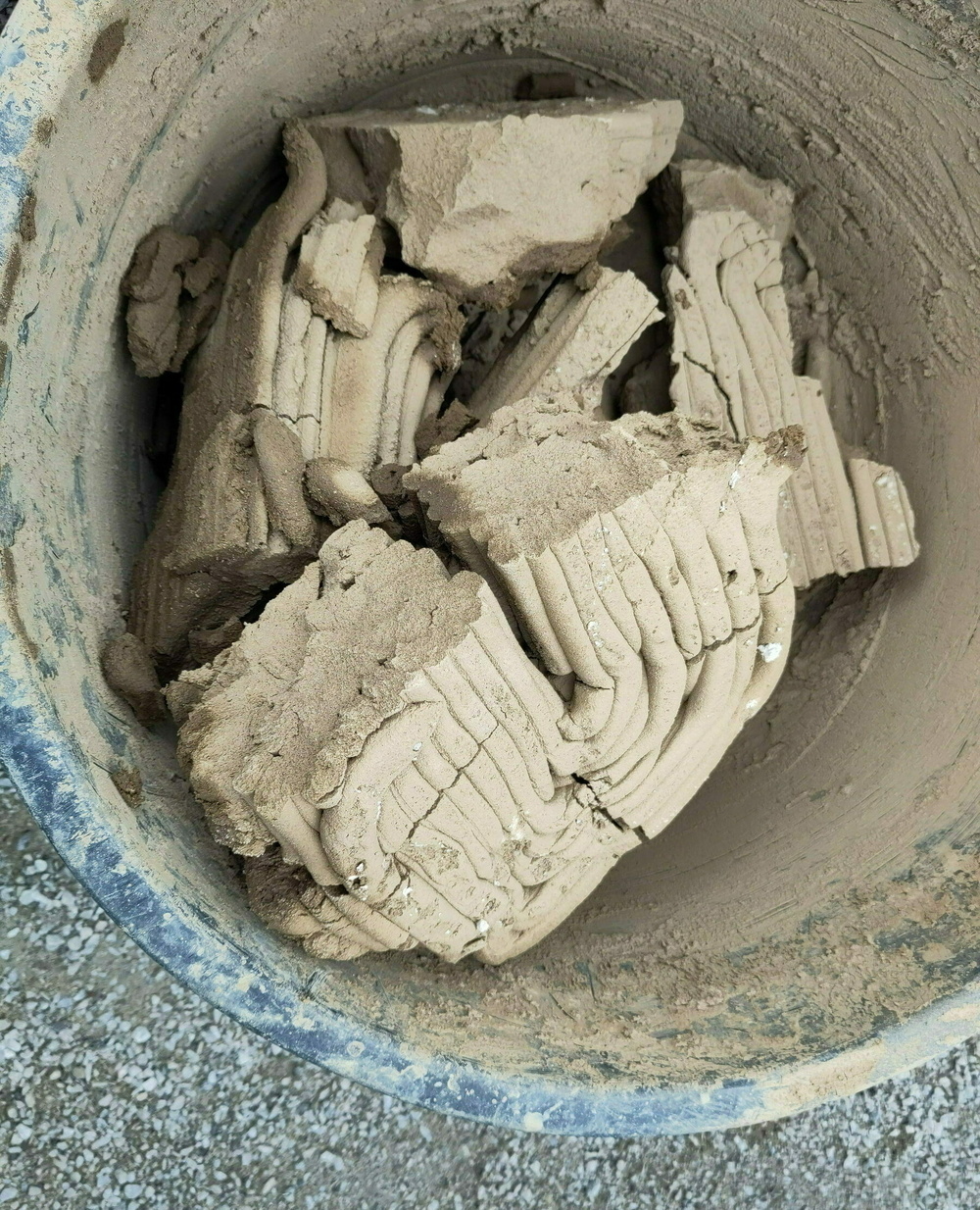
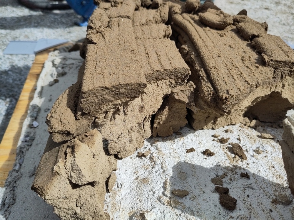
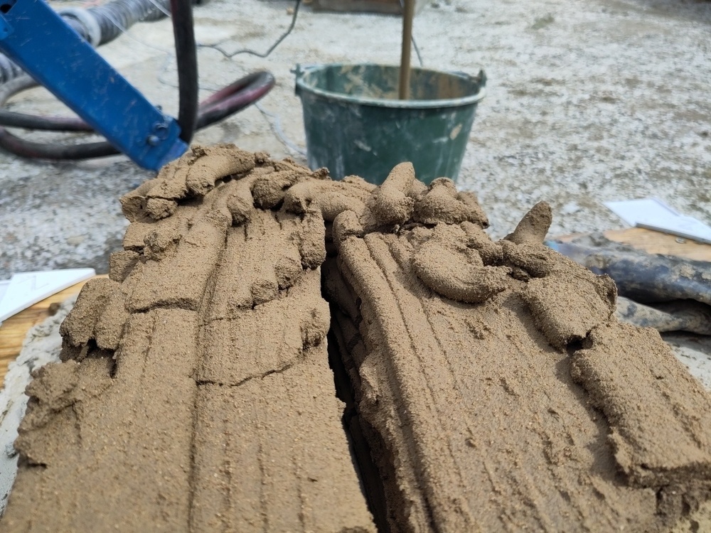
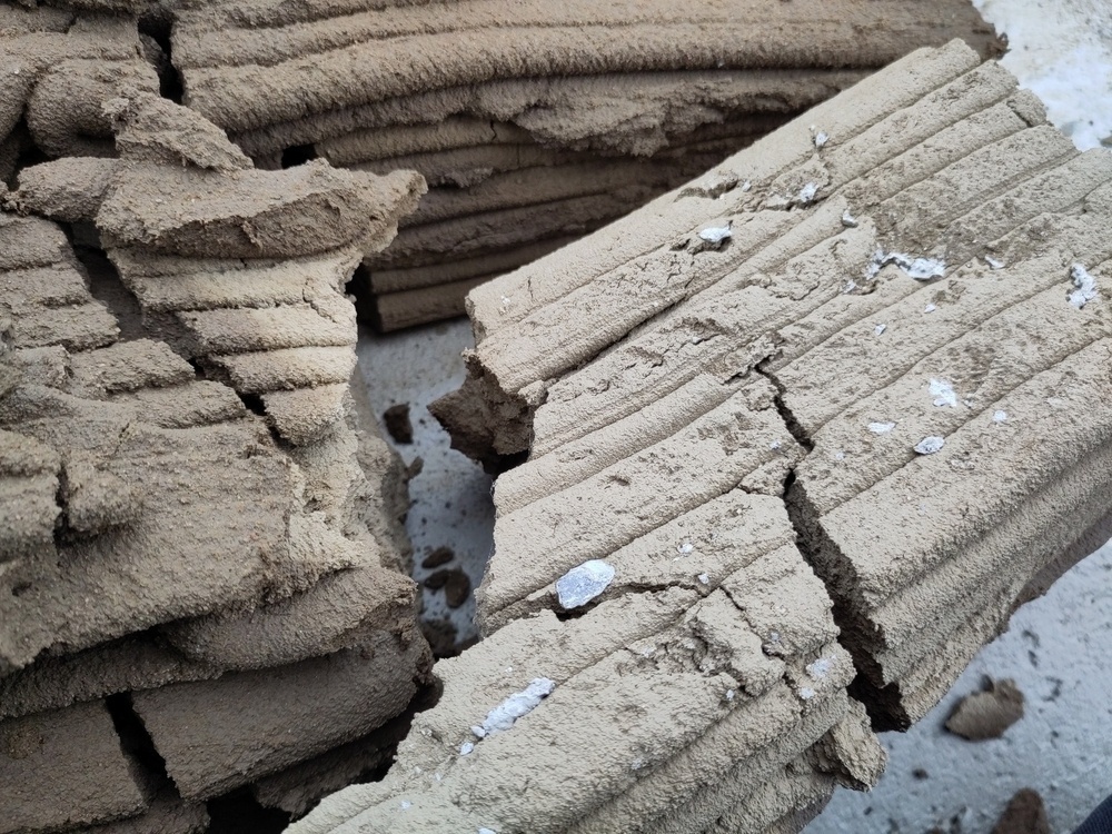
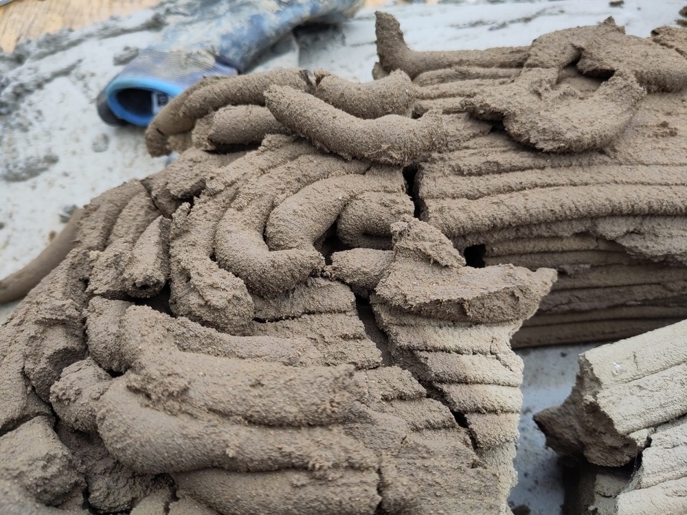
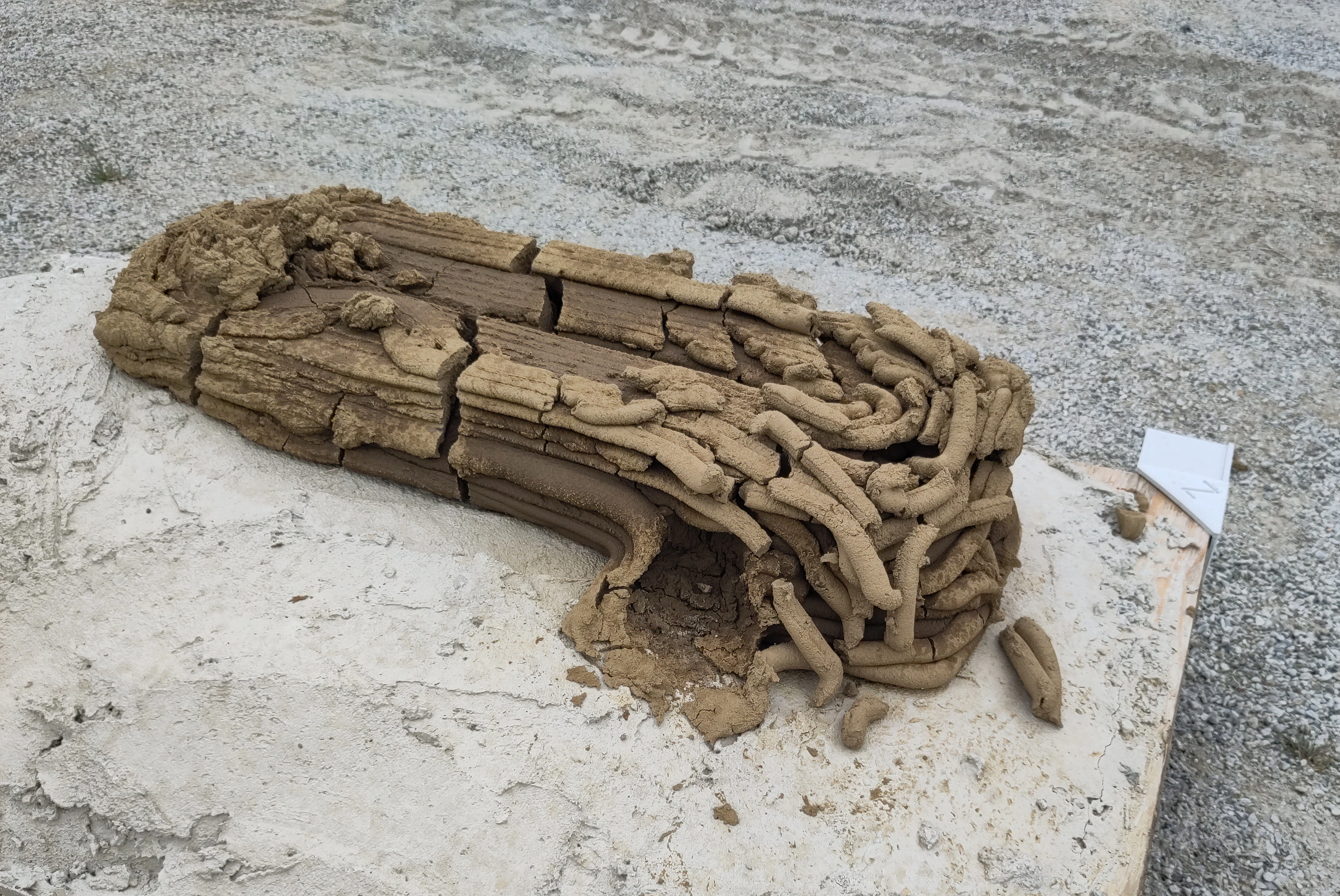
Last pictures of print 4
Finishing up support for extrusion factors per PrintFrame
-
clay_3dp_setup - bdc62a: RAPID code for the IRC5
-
erratic_TS25_ctrl_firmware - 062ff7b: Cast group input to
int8_t(signed) and update minimum RPS to-30.0 -
clay_3dp_print - b926b20: PrintFrame, set AO for each MoveL
Notes
Using the group output/input as an (8 bit) signed integer made everyone a lot simpler. The following (virtual) signals could be removed:
do_extrudeRelSpddo_retract
Leaving the following signals on the IRC5:
| Type | (Logical) Range | Notes | |
|---|---|---|---|
ao_TCPSpd |
system analog | 0.0-3.0 | Mapped to TCP run (mm/s) |
ao_flowRate |
virtual analog | 0.0-1.0 | Manual tweaks during run |
ao_printPtSpd |
virtual analog | -1.0 - +1.0 | Set before every move |
do_forceExtrude |
virtual digital | ||
do_forceRetract |
virtual digital | ||
go_TCPSpeed |
physical group output | -127 to 127 | Calculated speed |
Clay 3DP setup
The RAPID module has gone through two iterations since it was last
commited. The task is now semi-static, meaning it runs in the
background when the controller starts (semi means it restarts when the
controller restarts).
The ABB IRC5's group outputs can only be set to unsigned integers. You
can still cast it int8_t manually. Map positive numbers to 0-127,
and calculate negative numbers by subtracting it from 255. Meaning
-30 becomes 225. This can then be converted back on the
microcontroller using a simple c++ cast ((int8_t)value).
Erratic TS25 control firmware (for a Controllino Micro)
As described above, a cast is enough to get the correct values.
There were however some earlier problems with using analog in as digital
in, since the digital threshold needs to be set explicitly for the pin
(The Controllino wiring implementation sets it to 0UL.
See erratic_TS25_ctrl_firmware: de38d29).
const uint8_t AI_RESOLUTION = 23;

// Calculate threshold value for 7V in a 0-24V, 7V comes from ABB spec, I think
const uint32_t AI_DIGITAL_THRESHOLD = (7.0 / 24.0) * ((1UL << AI_RESOLUTION) - 1);

setDigitalThreshold(pin, AI_DIGITAL_THRESHOLD); // noop for digital inputs
I might need to raise this with Controllino.
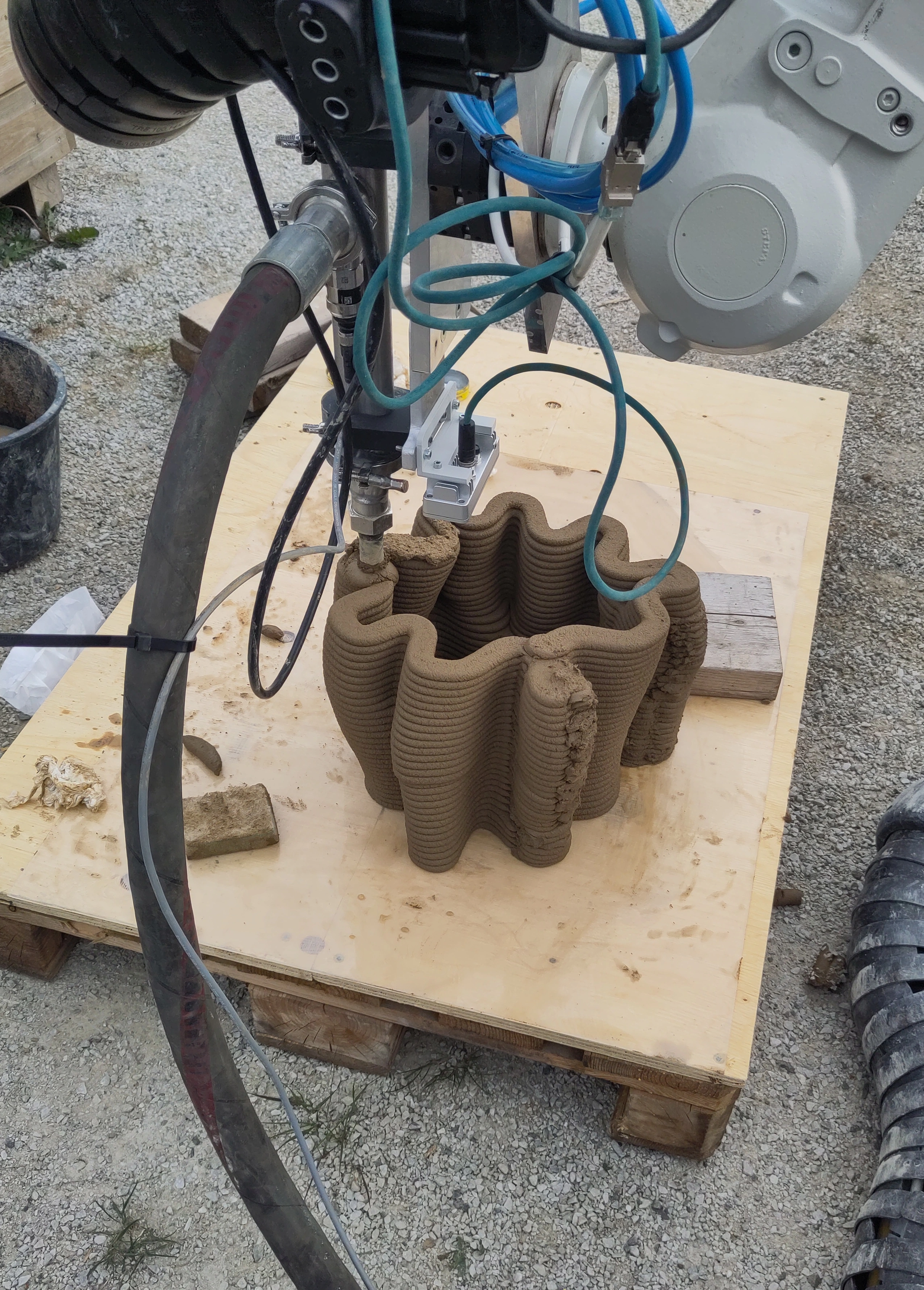
Clay 3DP print
I finally bit the bullet and created my PrintFrame, a variation of
compas_slicer's PrintPoint. It's just a (compas.geometry)
frame with an extrusion_factor property. Thanks to the work on
compas.data this neatly serialises and deserialises from json.
I might have gone too far with PrintLayer, but in my defense it's
just a list with a @classmethod that creates itself out of a list of
frames and a list of float values.
And does it work?
Yes! But I might need to fine tune the SPEED_COEFFICIENT set in the
TX_SPEED task.
Side project with Johanna Jonsson.
Print 4: Non planar printing on top of casted surface
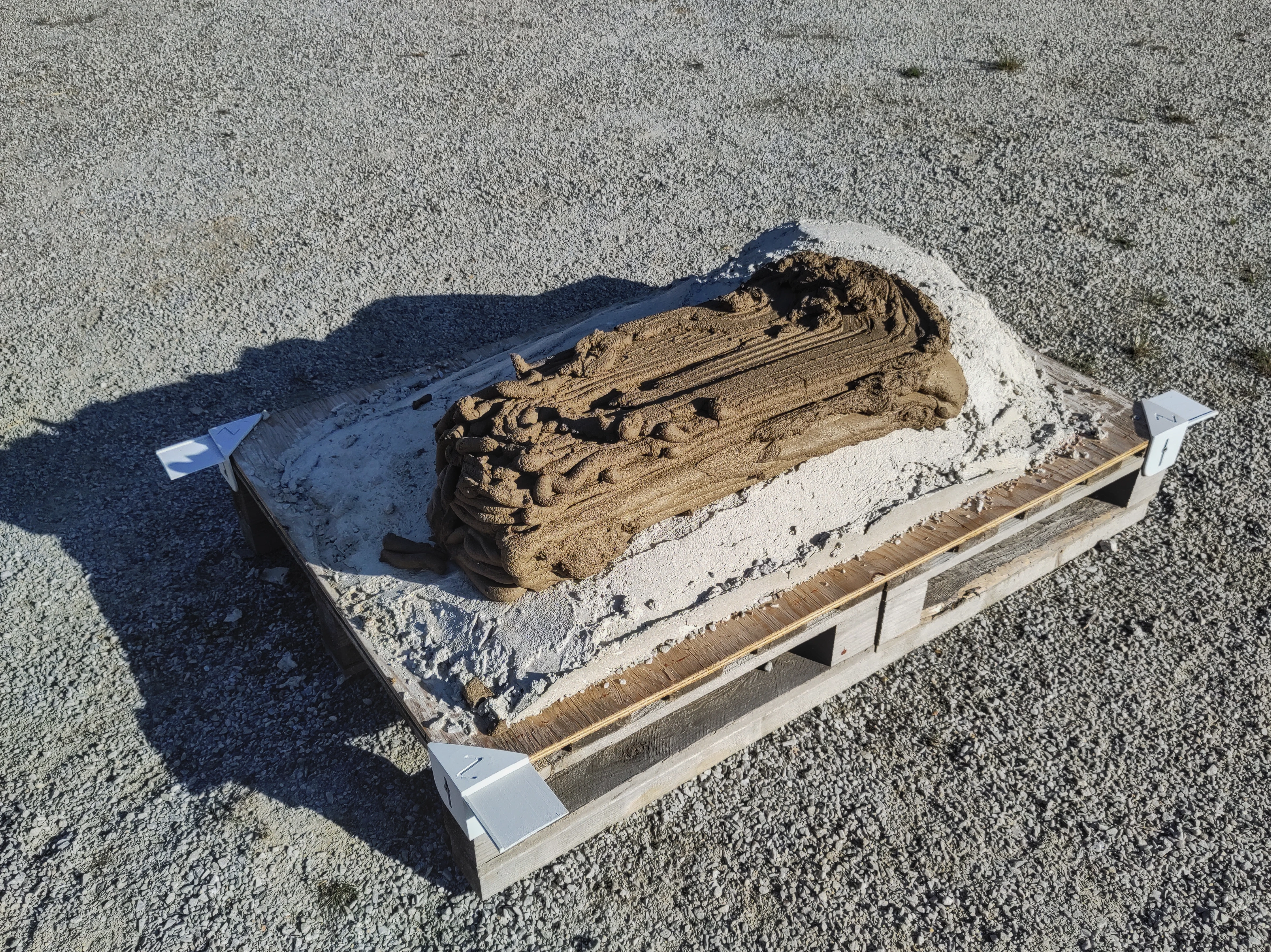
Planes generated using grasshopper script: 01offsetting method nonplanar rethink simpler shape blend offsets short scaled.gh
Oriented to scan using:
- match scan to wobj.gh based on flexobed2/3dModel.obj (photogrammetry)
Design steps
- Design shape of desired geometry
- Create a boolean difference between scanned geometry (massaged to be a closed BRep) and desired geometry.
- Take the border of the surface left at the bottom of the boolean difference, where the desired geometry met the scanned geometry.
- Group it with the borders of other horisontal surfaces in the model. In my case there were 3 more, since the model was a rectangle with filleted corners if seen from abovee, with another BRep on top that also had cutouts for a wooden beam.
- Offset these curves. The non planar curve the bottom needs to be coupled with the surface it was extracted from in order to determine the offset directions properly.
- Blend the curve pairs, this is done using factors
0.0-1.0where 0 is one curve and 1 the other. Calculate the factors based on a nominal layer height, by taking the largest distance between the curves and dividing it by the height.
Hacks
(Not a hack) TX_SPEED is now SEMI-STATIC
Meaning it is always running, and starts from where it stopped whenever the IRC5 is booted.
This is needed to be able to stop the extruder motor when the robot is in emergency stop (or the program is stopped some other way).
Flow rate increase
Changed the n_max_speed in TX_SPEED on 0.10. This is a clear hack,
since the speed the variable is referencing is the TCP speed of the
robot. It works however since the TX_SPEED task remaps from
n_min_byte to n_max_byte (0-254) to n_min_speed to n_max_speed
(now 0.10-0.250 (mm/s)).
Might make more sense to change value on Controllino Micro or better yet, base it on a virtual group output on the robot that can be set from the flexpendant.
If frame Z were more than 30° degrees from flipped world Z then…
… it was replaced with a frame with Z axis $[0, 0, -1]$.
This made for some quite extreme re-orientations during run
Updates
2025-05-12
No rain since print according to SMHI: Weather data
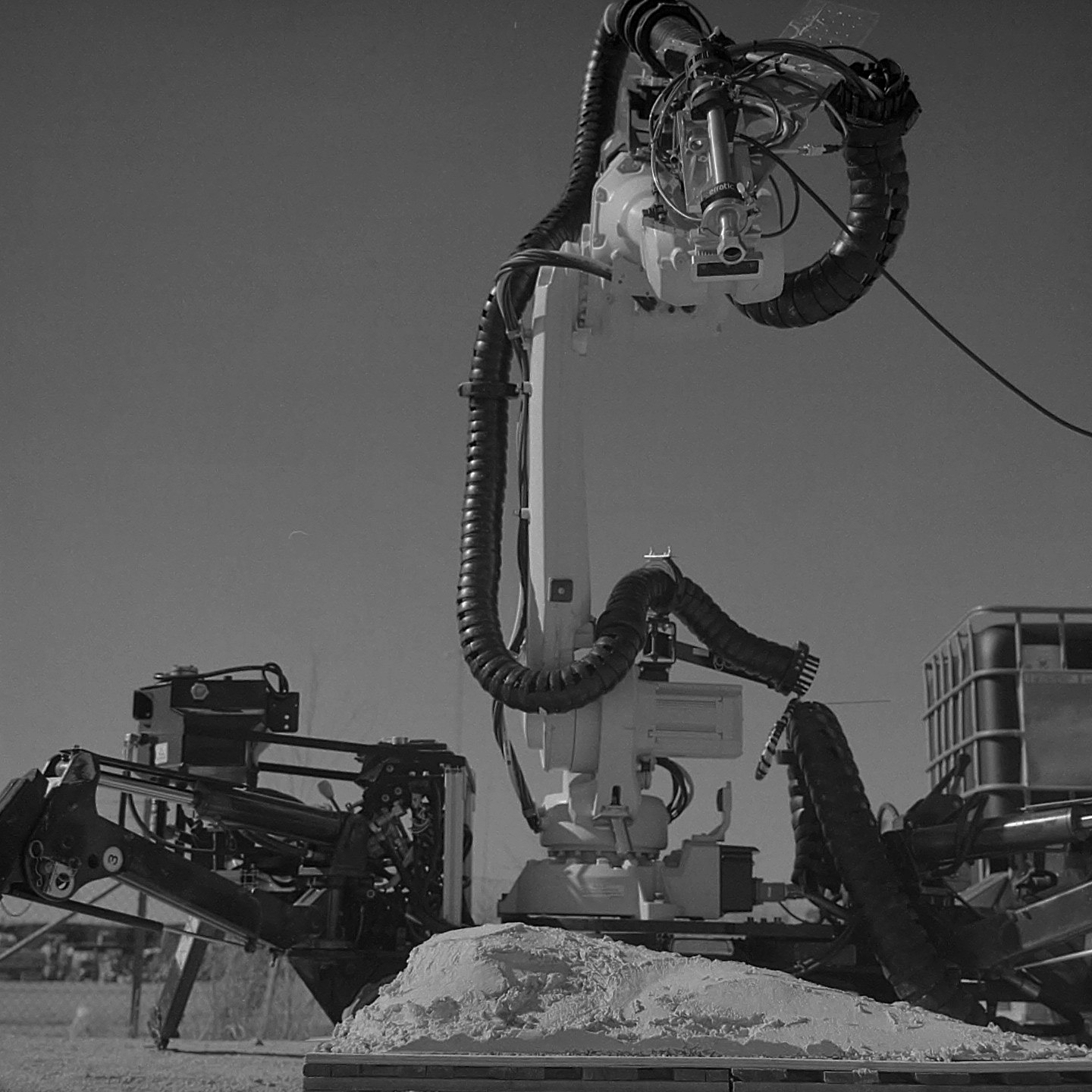
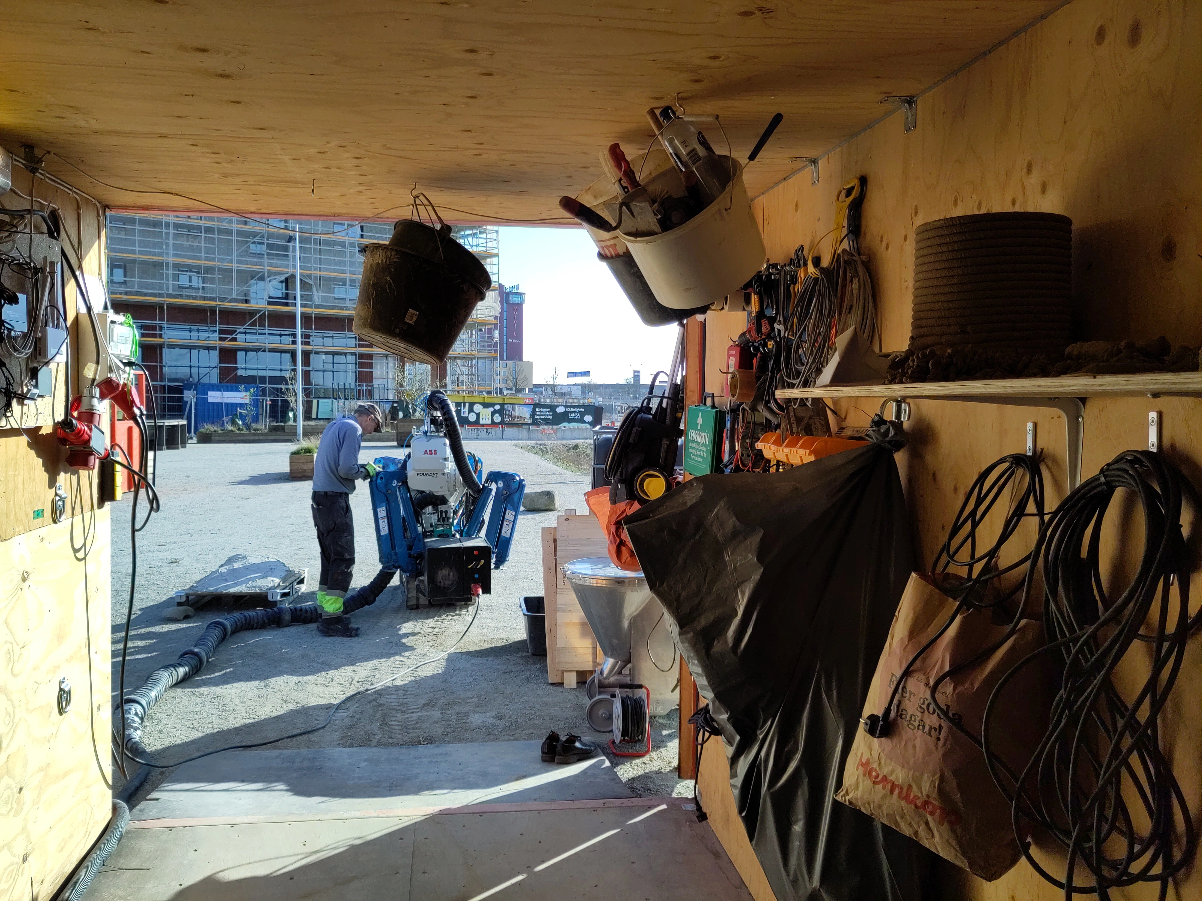
Photos by Klas Holger Jönsson
Klas Holger Jönsson stopped by and took some images. He kindly sent along scans of the developed film.


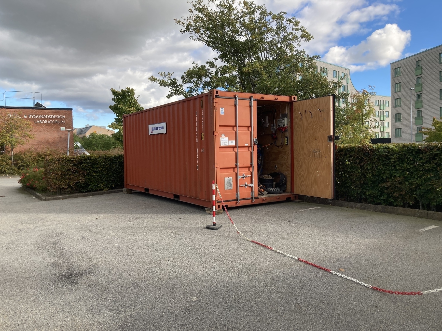
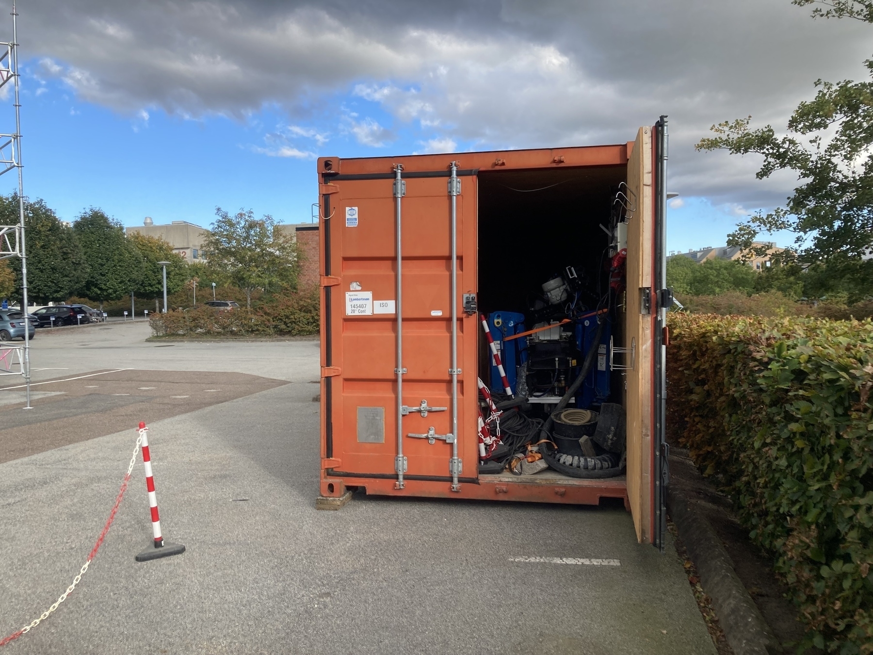
Organising inside the Construction Robotics lab container to make work easier.
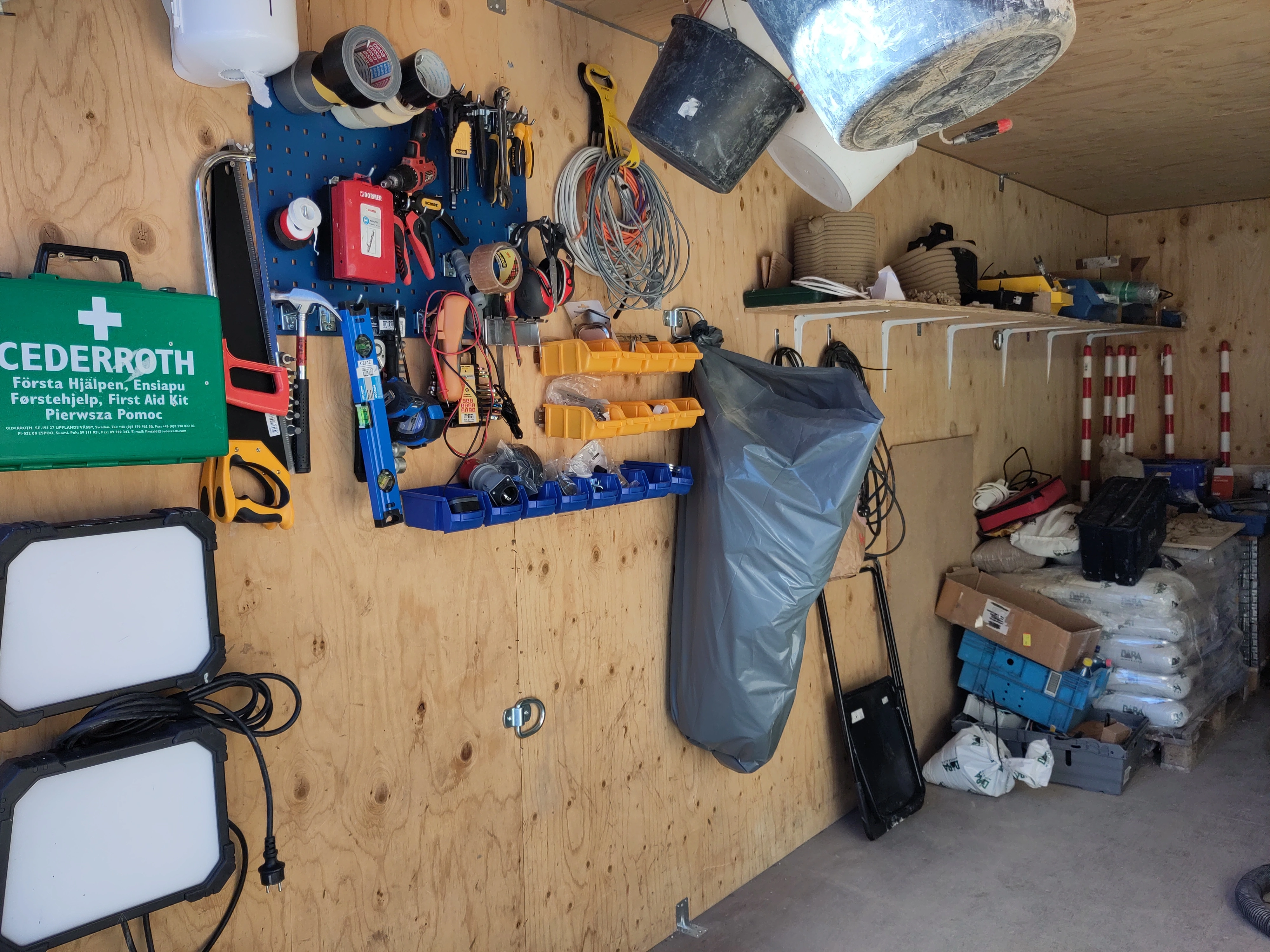
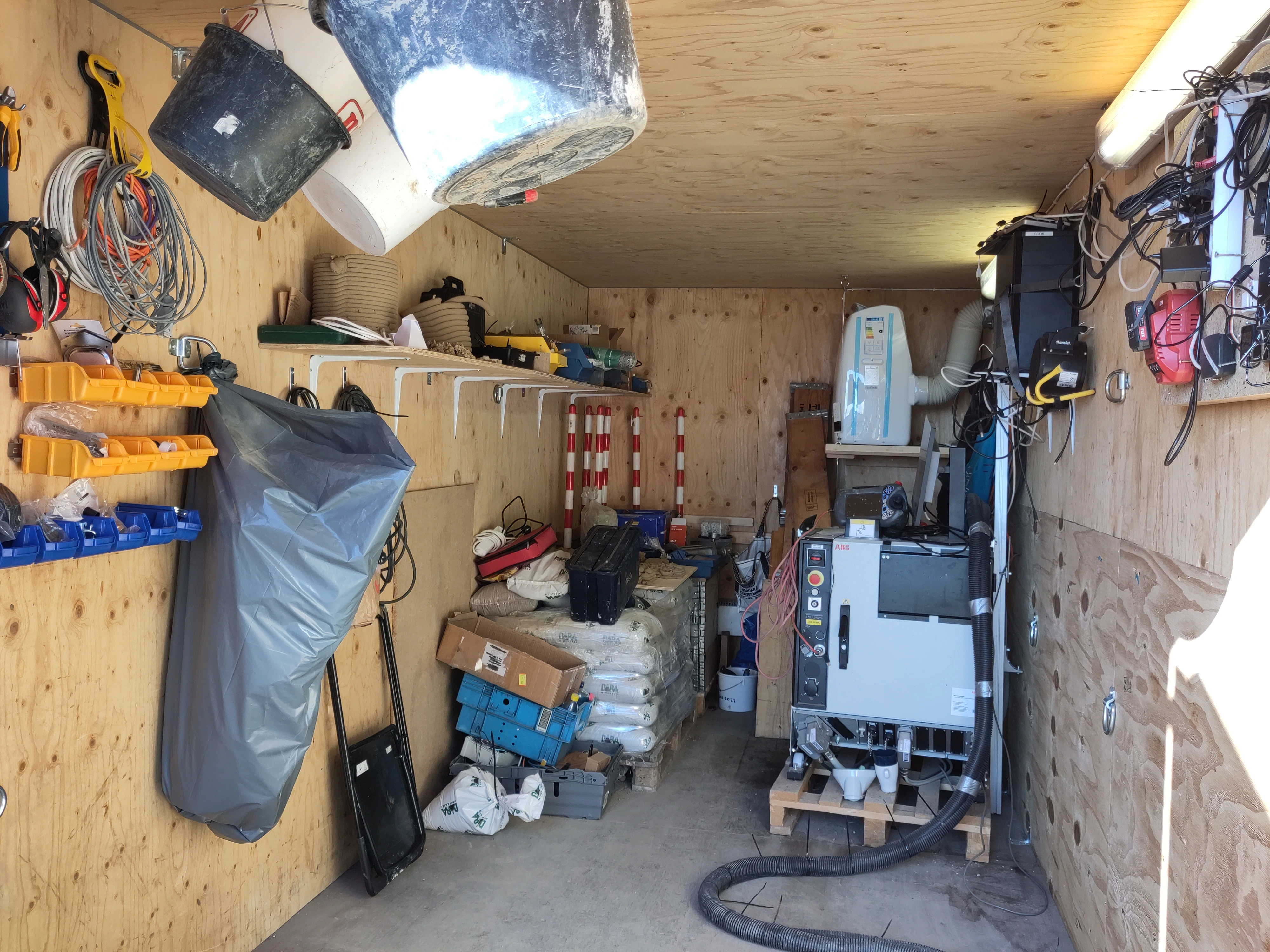
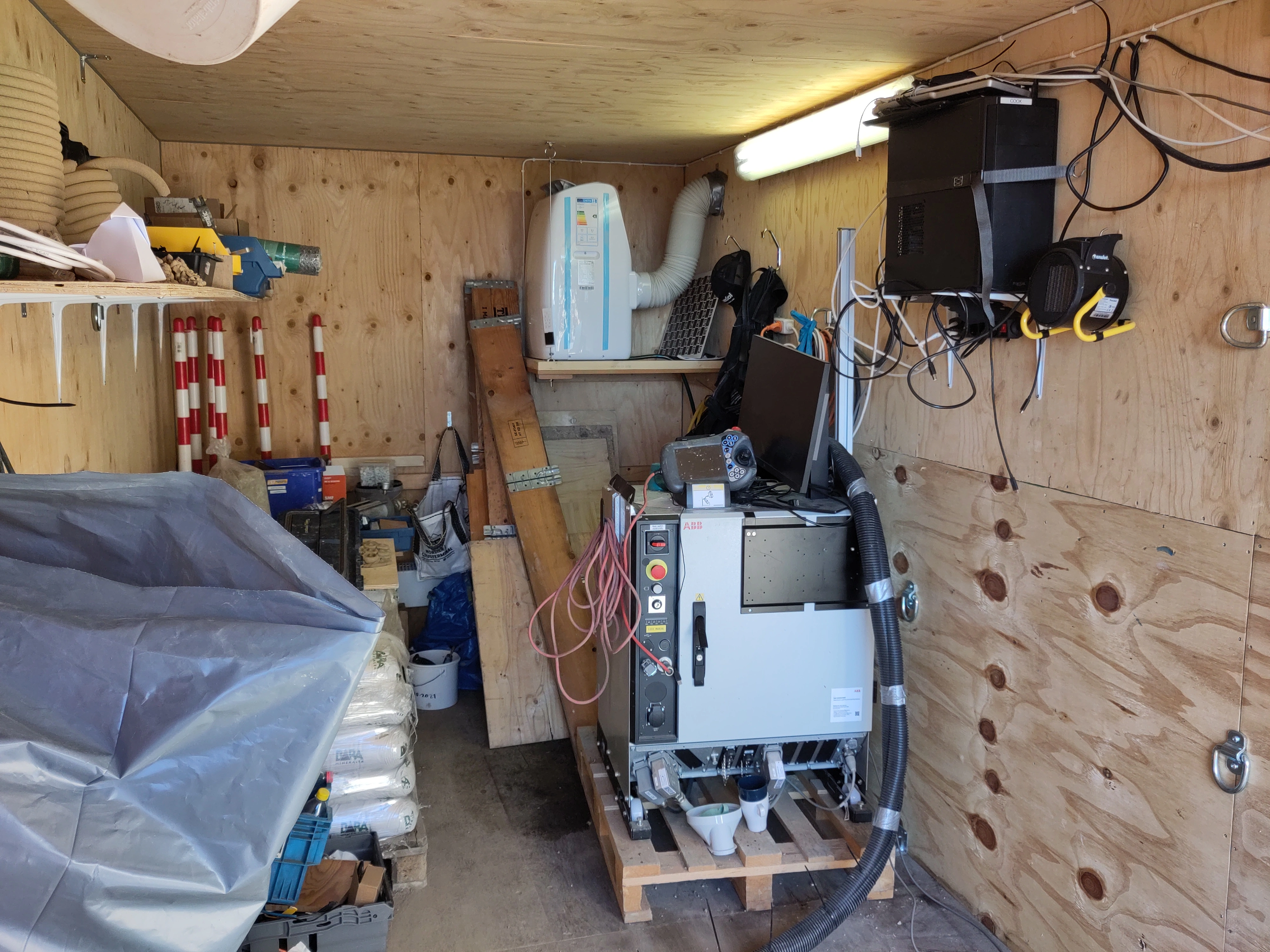
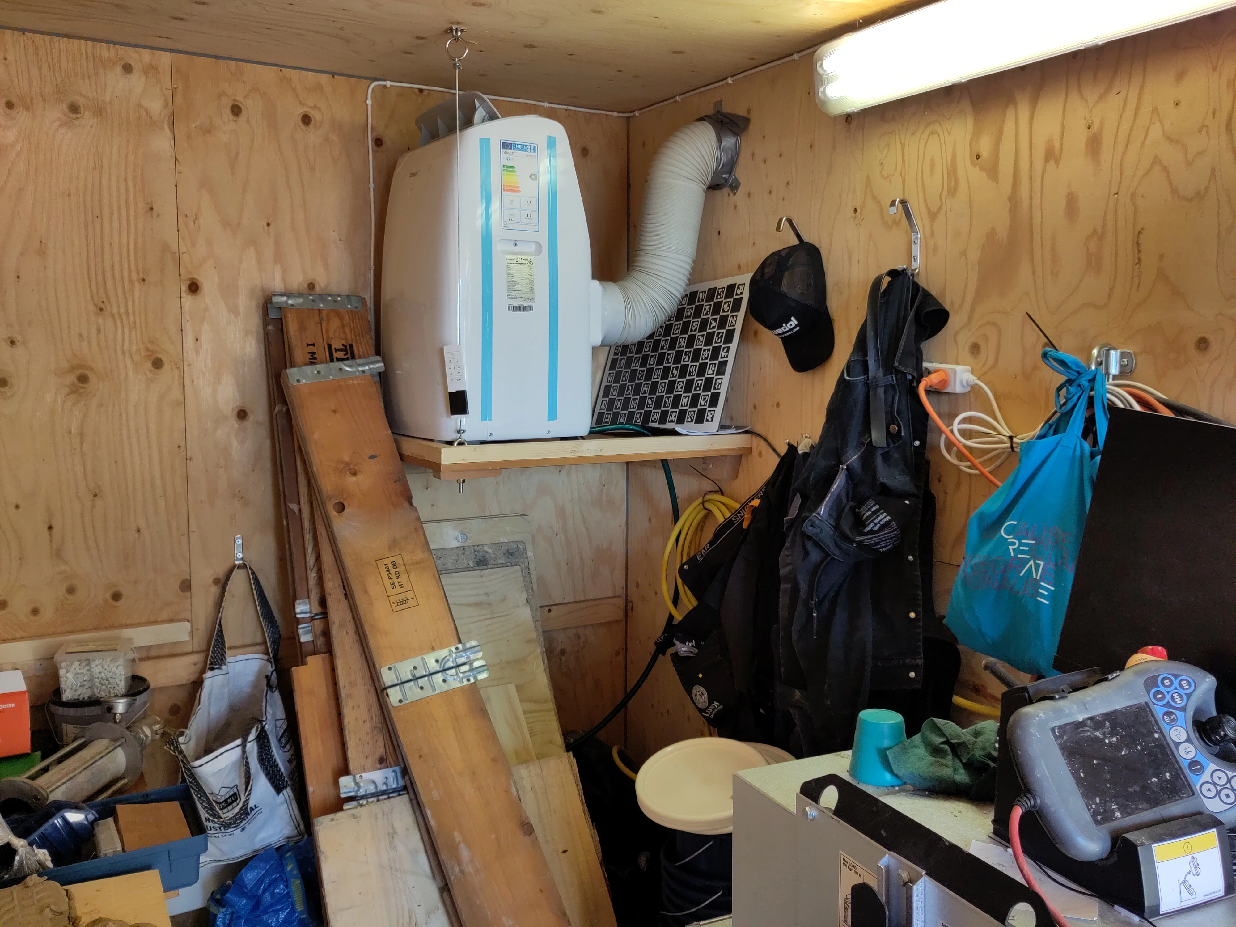
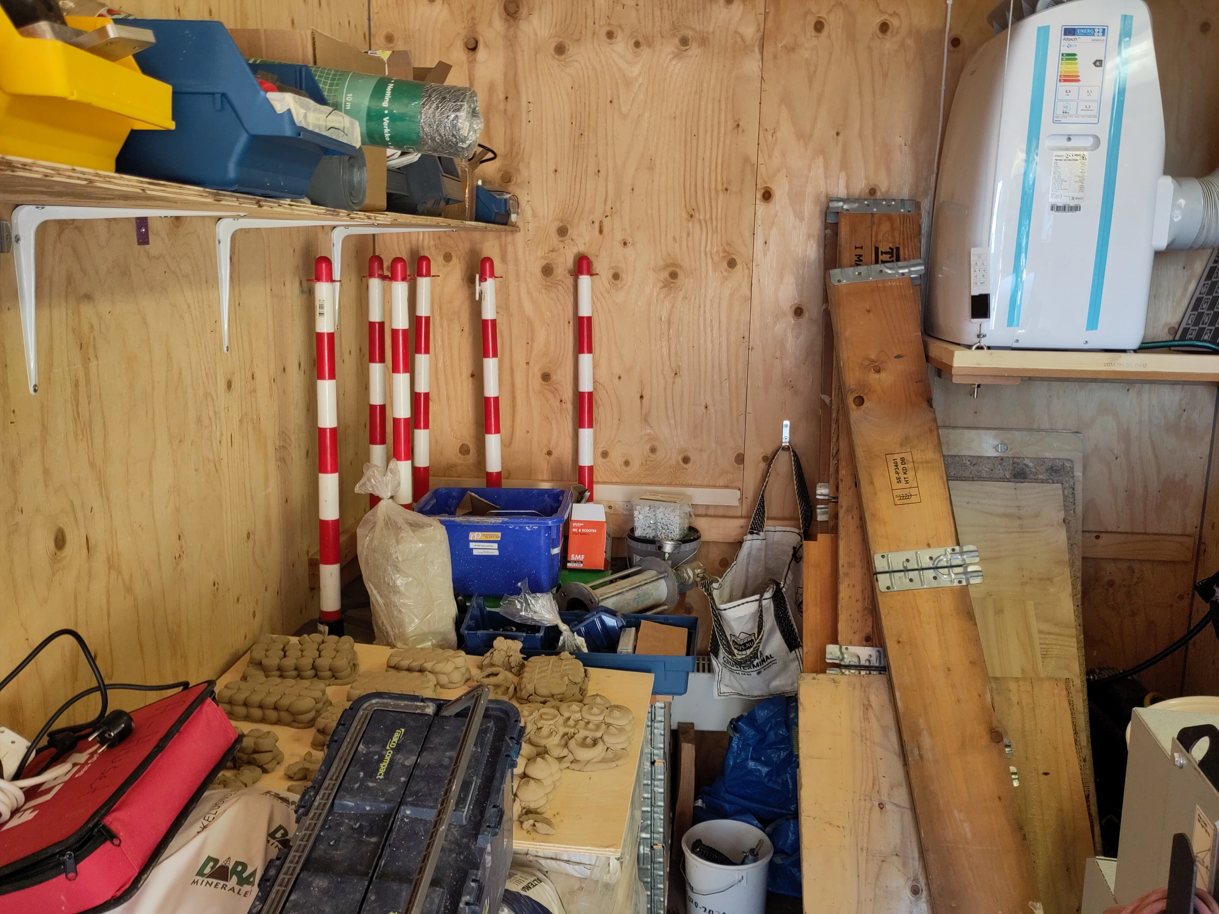
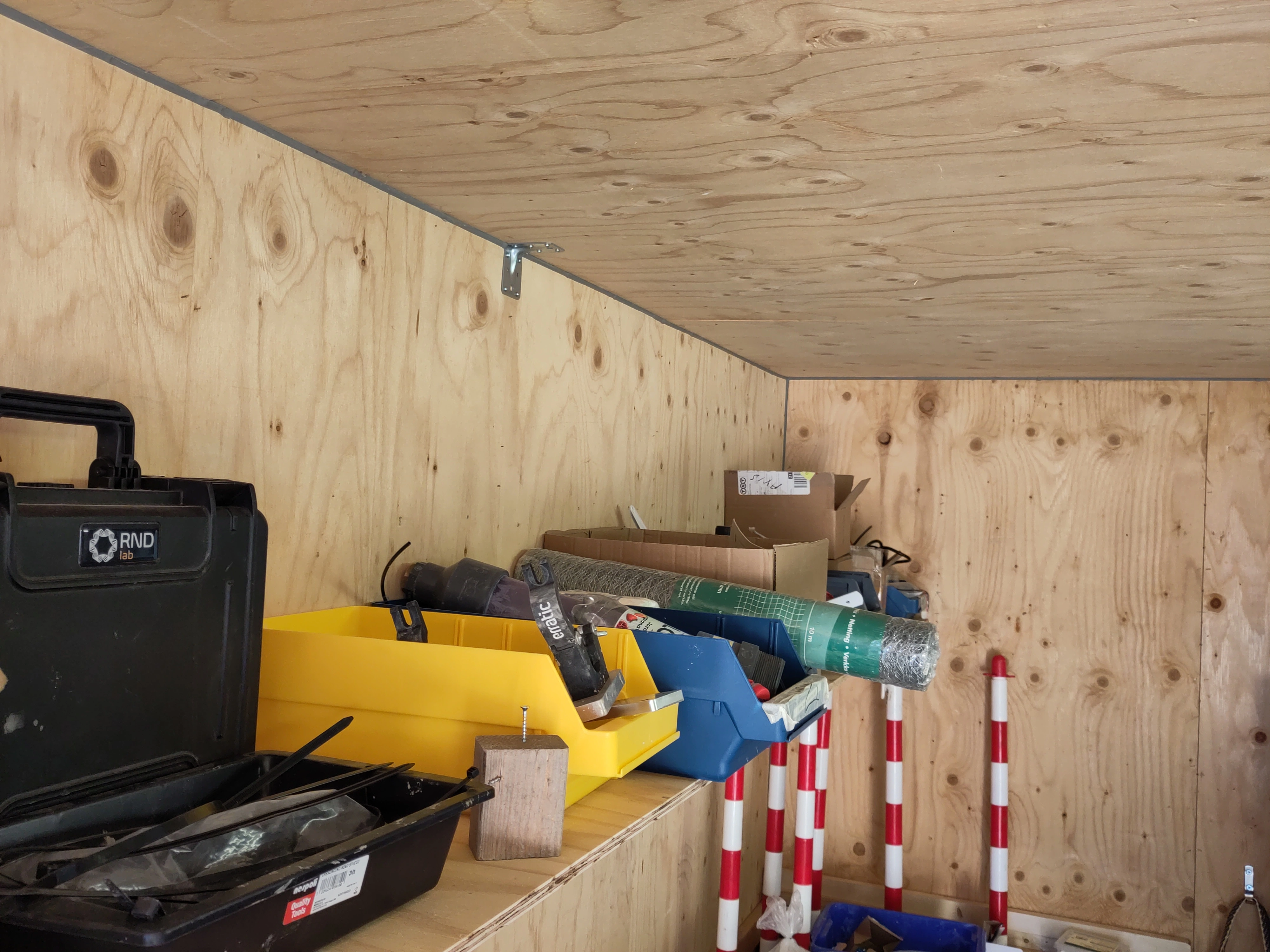
Wishing for a neat solution, distracted from immediate concerns
I can’t figure out how R2.CBUS is connected, it should be on XP (customer power) but I can’t make a circuit.. Doesn’t help that I’m not sure which IO option we have. My best guess is the “Multibus, new” as per the circuit diagram for IRB 4600 (requires account).


Making fake bedrock.


Glitchy lofts


